Posts

Showing posts from 2015

Voice controlled smart home

Image
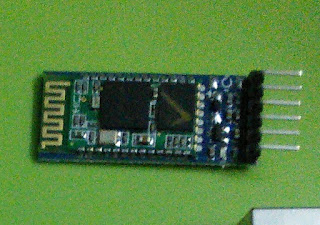
Heyyyy all..!! again iam back with new prototype of thing which is "VOICE CONTROLLEd SMART HOME"in this post you are going to learn complete detailed description of Bluetooth module (HC-05) and also some micelinious already explained in earlier posts Things that you need are:  *Arduino board *HC-05 Bluetooth module *Relays ( as many as home appliances) So our main aim is  to interface the Bluetooth module to our deserved one i.e ARDUINO Here I made my own ARDUINO with atmega328p as heart also I programmed this board using another ARDUINO board which has onchip ftdi converter(USB compatible) I hope you will understand this becoz I have given a clear theory about making ARDUINO'S Interfacing of Bluetooth module with ARDUINO is very easy. Hc-05 module as total 6 terminals so out of six we are using only 3 terminals they are VCC,GND, and TX.remember there is no need of using RX pin of module because we are not receiving any data from ARDUINO. So VCC is connected t

RF REMOTE..

Image
Want to make everything wireless..??? Huh.!! Then u r at right place. There are many wireless technologies like ir,DTMF,rf etc of these IR and DTMF are covered in earlier posts. So now its time for radio frequency communication.. Dont be get puzzled In this post I will direct you how make simple RF remote.. So for making remote,components that you required are *HT121D *HT121E *RX TX MODULES *1.1M ohm resistor *55k ohm resistor Now its time to know about encoders and decoders.encoders is a thing which creates some data at transmitter end. Decode is opposite for those encoders it simply decode the data which has been transmitted by encoders..so from this we conclude that encoders should always lies at transmitting section and decoders lie at receiver section MAKING A TRANSMITTER: MAKING A RECEIVER: This is how rf MODULES looks

ADC....¡¡

Image
The Analog World Microcontrollers are capable of detecting binary signals: is the button pressed or not? These are digital signals. When a microcontroller is powered from five volts, it understands zero volts (0V) as a binary 0 and a five volts (5V) as a binary 1. The world however is not so simple and likes to use shades of gray. What if the signal is 2.72V? Is that a zero or a one? We often need to measure signals that vary; these are called analog signals. A 5V analog sensor may output 0.01V or 4.99V or anything inbetween. Luckily, nearly all microcontrollers have a device built into them that allows us to convert these voltages into values that we can use in a program to make a decision. What is the ADC? An Analog to Digital Converter (ADC) is a very useful feature that converts an analog voltage on a pin to a digital number. By converting from the analog world to the digital world, we can begin to use electronics to interface to the analog world around us. Not every p

Number conversation.. ¿¿

Image
When we write numbers, we have ten different digits that we can put in each place (0-9). After that we need to add a new column of digits and we keep going. This is called the decimal system (or base 10). What would happen if instead of using ten digits we used eight, or two, or even sixteen? Well, what happens is instead of a decimal system we would have what's called binary, octal, or hexadecimal systems (base 2, base 8, and base 16). We use subscripts to denote the system we are using: 9876 10  is decimal (if we don't use a subscript we assume we are using decimal), 7653 8  is octal, 1010 2  is binary, and BEEF 16  is yummy  hexadecimal. Binary  – binary just has 1s and 0s. But much of our world is binary. Light switches are either up or down, your computer is either on or off, our servers are either currently up or down (hopefully up). Because computers are made up of billions of little switches (called transistors), they do calculations in binary. Everything in your

Alcohol sensor (MQ3) interfacing..¡¡¡

Image
Heyyy..now am here to explain the "interfacing of alcohol sensor to popular ARDUINO. It's very easy. Alcohol sensor simply mq3 sensor is analog sensor which outputs the voltage.o/p of the sensor is fed to analog pin of ARDUINO.. Here Is the pic how the sensor looks It contains six pins so we to work for sometime to make this six pins as three pins i.e VCC,GND,Vout.below fig shows how to connect this sensor To ARDUINO board Now we have 3 pins for the sensor,connect VCC to 5V,GND to GND pin of ARDUINO and data to any analog pin of arduino Just dump the below Sketch to ur board and observe the output of the sensor in serial moniter Here is the code void  setup ( )   {    // initialize serial communication at 9600 bits per second:    Serial . begin ( 9600 ) ; } // the loop routine runs over and over again forever: void   loop ( )   {    // read the input on analog pin 0:    int  sensorValue  =   analogRead ( A0 ) ;    // Convert the analog readin

Making your own arduino...!!!

Image
Hiiiii...    Now we are going build a arduino board..before knowing this WHAT IS ARDUINO..??? it a combination of some hardware (say microcontroller)along with compatible software(ARDUINO Ide) Above pic shows the basic ARDUINO board with atmega328p as its heart.so,now in this post I will tell u how to make your own board.for doing this you should require Atmega328p ic with base 16 MHZ crystal oscillator 22pf capacitors 7805 Male headers etc....  If you buy a atmega328p,initially it is not ARDUINO Ide compatible microcontroller. So to make it a ARDUINO compatible mc you must burnboot loader to that ic..it's very easy and simple procedure for that process is explained below  To burn bootloder u must have an ARDUINO board and breadboard with required components. ARDUINO to breadboard connections is shown in below pic Burning the Bootloader If you have a new  ATmega328  (or  ATmega168 ), you'll need to burn the bootloader onto it. You can do this using an A

Controlling home appliances wireless......!!!

Image
Hiiiii frnds ...today iam with new prototype . i.e remote controlling of home appliances..this can control almost all electrical appliances using some common wireless technologies like IR remote control DTMF based controlling.. Tools I used here for developing this project is arduino ide.. Components for this project are Atmega328p ic's( one for IR and other for DTMF) Tsop sensor DTMF decoder which I used in earlier post Relays (as many appliances) 16x2 lcd's (optional) Below is the code for both IR and DTMF //for DTMF #include <LiquidCrystal.h> // initialize the library with the numbers of the interface pins LiquidCrystal lcd(6, 7, 5, 4, 3, 2); void setup() { pinMode(9,INPUT); pinMode(10,INPUT); pinMode(11,INPUT); pinMode(12,INPUT); pinMode(A5,OUTPUT); pinMode(A4,OUTPUT); pinMode(A3,OUTPUT); pinMode(A2,OUTPUT); // set up the LCD's number of columns and rows: lcd.begin(16, 2);