ADC....¡¡
The Analog World
Microcontrollers are capable of detecting binary signals: is the button pressed or not? These are digital signals. When a microcontroller is powered from five volts, it understands zero volts (0V) as a binary 0 and a five volts (5V) as a binary 1. The world however is not so simple and likes to use shades of gray. What if the signal is 2.72V? Is that a zero or a one? We often need to measure signals that vary; these are called analog signals. A 5V analog sensor may output 0.01V or 4.99V or anything inbetween. Luckily, nearly all microcontrollers have a device built into them that allows us to convert these voltages into values that we can use in a program to make a decision.
What is the ADC?
An Analog to Digital Converter (ADC) is a very useful feature that converts an analog voltage on a pin to a digital number. By converting from the analog world to the digital world, we can begin to use electronics to interface to the analog world around us.
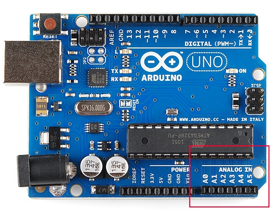
Not every pin on a microcontroller has the ability to do analog to digital conversions. On the Arduino board, these pins have an ‘A’ in front of their label (A0 through A5) to indicate these pins can read analog voltages.
ADCs can vary greatly between microcontroller. The ADC on the Arduino is a 10-bit ADC meaning it has the ability to detect 1,024 (210) discrete analog levels. Some microcontrollers have 8-bit ADCs (28 = 256 discrete levels) and some have 16-bit ADCs (216= 65,535 discrete levels).
The way an ADC works is fairly complex. There are a few different ways to achieve this feat (see Wikipedia for a list), but one of the most common technique uses the analog voltage to charge up an internal capacitor and then measure the time it takes to discharge across an internal resistor. The microcontroller monitors the number of clock cycles that pass before the capacitor is discharged. This number of cycles is the number that is returned once the ADC is complete.
Relating ADC Value to Voltage
The ADC reports a ratiometric value. This means that the ADC assumes 5V is 1023 and anything less than 5V will be a ratio between 5V and 1023.
Analog to digital conversions are dependant on the system voltage. Because we predominantly use the 10-bit ADC of the Arduino on a 5V system, we can simplify this equation slightly:
If your system is 3.3V, you simply change 5V out with 3.3V in the equation. If your system is 3.3V and your ADC is reporting 512, what is the voltage measured? It is approximately 1.65V.
If the analog voltage is 2.12V what will the ADC report as a value?
Rearrange things a bit and we get:
Ahah! The ADC should report 434.
Arduino ADC Example
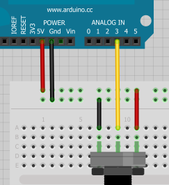
To show this in the real world let’s use the Arduino to detect an analog voltage. Use a trimpot, or light sensor, or simple voltage divider to create a voltage. Let’s setup a simple trimpot circuit for this example:
To start, we need to define the pin as an input. To match the circuit diagram we will use A3:
pinMode(A3, INPUT);
and then do the analog to digital version by using the analogRead() command:
int x = analogRead(A3); //Reads the analog value on pin A3 into x
The value that is returned and stored in x will be a value from 0 to 1023. The Arduino has a10-bit ADC (210 = 1024). We store this value into an int because x is bigger (10 bits) than what a byte can hold (8 bits).
Let’s print this value to watch it as it changes:
Serial.print(“Analog value: “); Serial.println(x);
As we change the analog value, x should also change. For example, if x is reported to be 334, and we’re using the Arduino at 5V, what is the actual voltage? Pull out your digital multimeter and check the actual voltage. It should be approximately 1.63V.


Comments
Post a Comment